Double Topped Flagpole Antenna
Last updated 5/11/19.
You will need the June 2019 issue of QST
to follow along with this narrative.
My suggestion are:
1- Make a copy the 4 QST pages on this article so you can mark it up.
If you are an ARRL members, just login and go to the June 2019 issue and
print the pages.
2- Print the
Manuscript for the 2018 Antenna Competition
Manuscript from the QST-In-Depth archive or print it from
Antenna Competition Manuscript.
3- Print this web page so you can make notes.
Your comments and questions are welcome and you can contact me on email
address
w1ejm@arrl.net
After that communication, we can come up with a more convenient way to proceed with your
comments questions.
In this narrative you will find all sorts of text, photos, graphs etc. that
just couldn't be fit into the article.
Lets start before page 1....
From the desk of Don Crosby, W1EJM
Brief Bio:
Teenager in NYC in 1956, Kn2VVN, 125' Windom @25' (across neighbors yards) directly fed at the 1/3 point with
2' of 300
Ω open wire to a B&W air coil balun then ~50' of 75 ohm coax to a 100w CW and
AM operation mostly on 75/80 and 40 meters.
Mid 1960's, married w/ kids, residing in Connecticut (W1EJM) on a modest
in town lot,
mostly SSB with dipole antennas and in later years, a TA-33 rooftop beam for 10-20 Meters.
Mid 1980's, at our final 20 years in Connecticut, at our country hilltop home on ~
3 acres, lots of wire in the air, still using the TA-33, now with a (new to me)
25 year old
Collins station.
In 1997 we retired to Florida into a deed restricted community.
75/80 and 40 meters were my happy places, so I focus on antennas to work
those bands and if they worked on 160 or the higher bands, wow, that be
great.
Impetus for this antenna design:
My home is on a small lot, ~ 1/5 acre. So any antennas for the lower bands
will need to be spliced into the available space and needs to be "low
observable".
I tried lots of "low observable" wire antennas and always tried to keep
my antenna work to early evenings when neighborhood folks were having dinner, maybe
watching TV.
Over the course of 22 years I
have not had issues in my community, so do what is minimal and don't make it a big antenna
party!
The subject here is the Double Topped Flagpole Antenna (DTFA). It
covers all HF bands without an auto-tuner at the antenna base.
This design does use an enclosure at the antenna base for a few relays to
switch in an L/C pair, an UnUn and a ground for the antenna when the station is
unpowered.
It meets my needs being nearly invisible, works all HF bands without an
auto-tuner located at the antenna The antenna can handle a KW with the exception
of 160 meters (100 Watts).
Safety First
 |
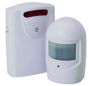 |
Safety Feature The Flagpole is electrically
energized and has potentially lethal voltage on its surface. Refer to the large
photo on the 1st page of the article. The vertical screen room member (to the
right of the flagpole ~ 6' above ground) has a Wireless Driveway Motion
Detector (PIR) mounted on it (purchased at Harbor Freight ~$15). The detector is
powered by 2 AA batteries and is good for more than a year. The receiver is in the ham shack and
is powered from the main switched AC line.
When the main switch for the station
is activated, the in shack Motion Sensor Receiver (RX) squawks once and drops the PTT line
relay.
A momentary push button switch resets the PTT relay so the Xmtr can run.
If a person or animal enters the field of view of the Motion Detector the RX
squawks and the PTT path is dropped.
So, if it's an animal, I turn on the lawn sprinklers and they
hit the road. |
DTFA Details
This document will be updated as new in information is available. I will cover Bands, Vswr, Gain and Radials as the subject needs discussion,
so you will find those topics coming up sort of impromptu, as needed to explain
why/how something was done.
Keep in mind that this antenna WILL have Vswr in some ham bands that
will need the use of a tuner. In all cases I was able to match it to my
transceiver or tube amp In-Shack using the methods described.
This DTFA uses an aluminum flagpole as it's vertical support and the
flagpole is both a radiator and a
feed line (could just be a 20' wire in thick walled fiberglass tubing). You can make a flagpole up from thin wall 2" aluminum tubing, don't need to
spend a lot of money on a fancy flagpole, just buy a small pulley at the top and a cleat
for the rope.
The flattop wires are #20/21 AWG tin-nickel finished copper trolling wire, ~0.030" diameter
rated at 32# test. As such, the wire
part of the antenna is very difficult to see. The wire doesn't melt at a KW SSB.
The flagpole needs to be insulated at the base and of course you will need
radials.
If you have grass around the radial area then read installing radials at the
grass/earth interface, one man install will do 100 feet per man-hour.
Note: In Florida a 20' Flagpole is permitted on any homeowners property
see Florida
Statute 720.304(2) .
Familiarize yourself with the details of this antenna by visiting the original
Antenna Competition Manuscript submission,. The manuscript is very
detailed and includes many graphs which show the pattern for angles from
30°
to
180°.
Now lets start our review of the QST article, 1st
page.
 |
The contest parameters limited the antenna footprint to
30' x 50' by 30' height.
So, I ran my competition antenna tests with the configuration shown on
the left.
Additionally, I had installed my DTFA design at 4 sites. 3 were such
that the wires could only be ~90° apart. See the manuscript for
site details.
The 3rd site (shown on the right) allowed the wires to be in a
straight line (180°) and I used a 360° pattern of 34 radials
scratched into the grass / earth interface.
|
|
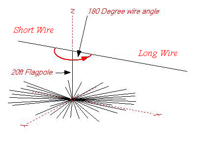 |
I ran with the wires at a 180°
included angle (straight line) at my home.
The antenna was modeled for angles as small as 30°.
At the time when the ARRL 2018 Antenna Competition was
announced I already had 3 installations running, a 4th followed by year end. Those 3
installs used 90°
to 110°
degree wire separation. Each installation was different
because of the pole height, wire slope, included angle and proximity to the house
roofs. There weren't any show stoppers, the tuning method was sufficient to
mitigate those issues. In the last installation, the longer wire was only
~4' above an asphalt
shingled roof.
The antenna requires a radial system
because the Flagpole is a radiating element in the design
(Click Here
> Link to how to plant radials in your lawn).
There isn't anything sacred about the flagpole height (16-24') or diameter as
long as it's conductive. Note that the wire lengths will need to change to
compensate for the height change.
In fact, I have run this flattop antenna with a single
#16 wire feed, as was the feed for the original Windom in the 1920's, BUT this
antenna requires a radial system.
If you are
inclined to do a single wire feed, you could use DX Engineering Fiberglass (telescoped
diameters) Tubing (0.120") as I did in early on experiments.
Figure 2 from QST are simplified. These are the Nec-2d modeling results for the
antenna in Figure 1 above.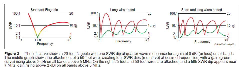
Same subject material as in Figure 2 above, but more detail is shown in the
original modeling program graphs.
 |
|
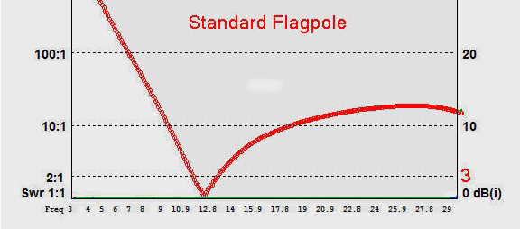
Nec-2d Model of a 2" Dia. 20' Long Aluminum Pole above my 34 radial
ground plane. So, what we expect to see and can verify is that we have
1/4 λ resonance.
Gain is 0dbi
50Ω
1:1 Vswr at resonance at 12MHz but it is very high below and running ~10 to 20:1 on 17
Meters and above.
It also tells us that there is 14Ω
in the ground loss path, What ya goin' to do....
Weave some more
radials into the vacant spaces. |
| |
|
|
| |
|
|
 |
|
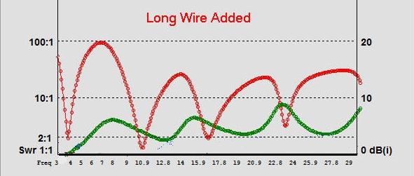
I wanted to work 75/80 Meter bands. I added a single wire. It provides 2:1 Vswr 3.8MHz and a few spots
above.
Gain at 3.8MHz remained unchanged at 0dbi
BUT, the Vswr dips up the line looked promising too. |
| |
|
|
| |
|
|
 |
|
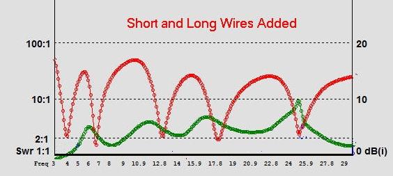
In order to get 40 meters, I add another (shorter) wire, trimmed it
for 40 Meters and the other Vswr dips moved into more useable spots.
The added wire didn't shift the 3.8MHz by more than a few KHz.
The new Vswr dips are at ~7, 13, 18 and 25MHz, each of those providing
increasing gain (directivity).
So, some judicious trimming may make things even better!
Hold your horses... the gain is really favored directionality, but if
it's in a direction you want that's good. |
| |
|
|
| |
|
|
Gain in Azimuth Direction;
Conditions:, 20' vertical with 34 wire radials, with and without the Double
Top Wires. All Omni except 40 M. Source NEC-2d model.
| Band |
|
Double Top Wires, Gain dbi |
|
Vertical Alone, Gain dbi |
|
Elevation (Peak) |
|
| 20 |
|
1.3dbi |
|
0.6dbi |
|
45° |
|
| 40 |
|
5.7dbi |
|
-4.3dbi |
|
90° |
Front/Back to side ~5db |
| 80/75 |
|
1.1dbi |
|
-12.5dbi |
|
35° |
|
| 160 |
|
-7.3dbi |
|
-23dbi |
|
25° |
|
Thus, this 75/80 and 40
Meter antenna is a winner given the Gain improvements over the Vertical alone.
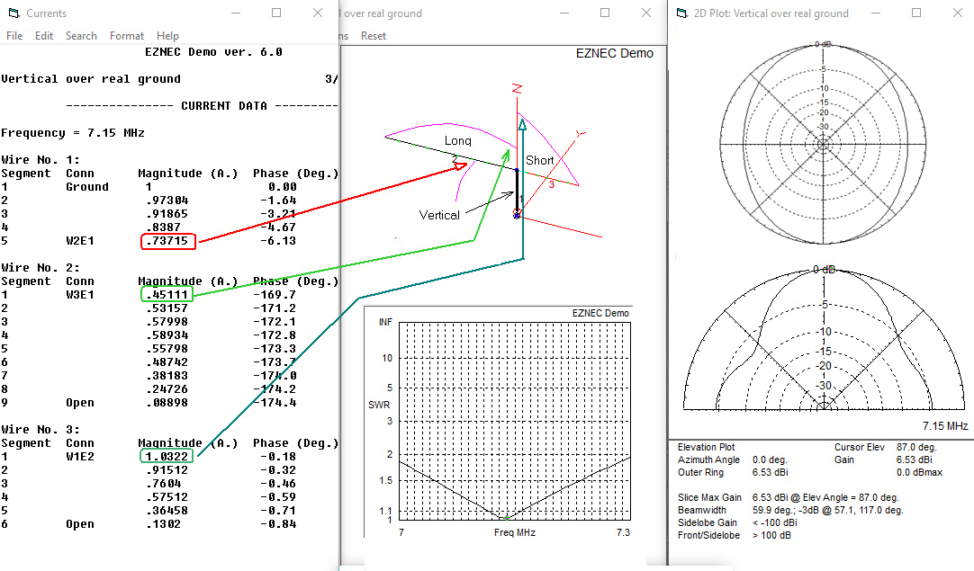
So, you ask.... just how does it work?
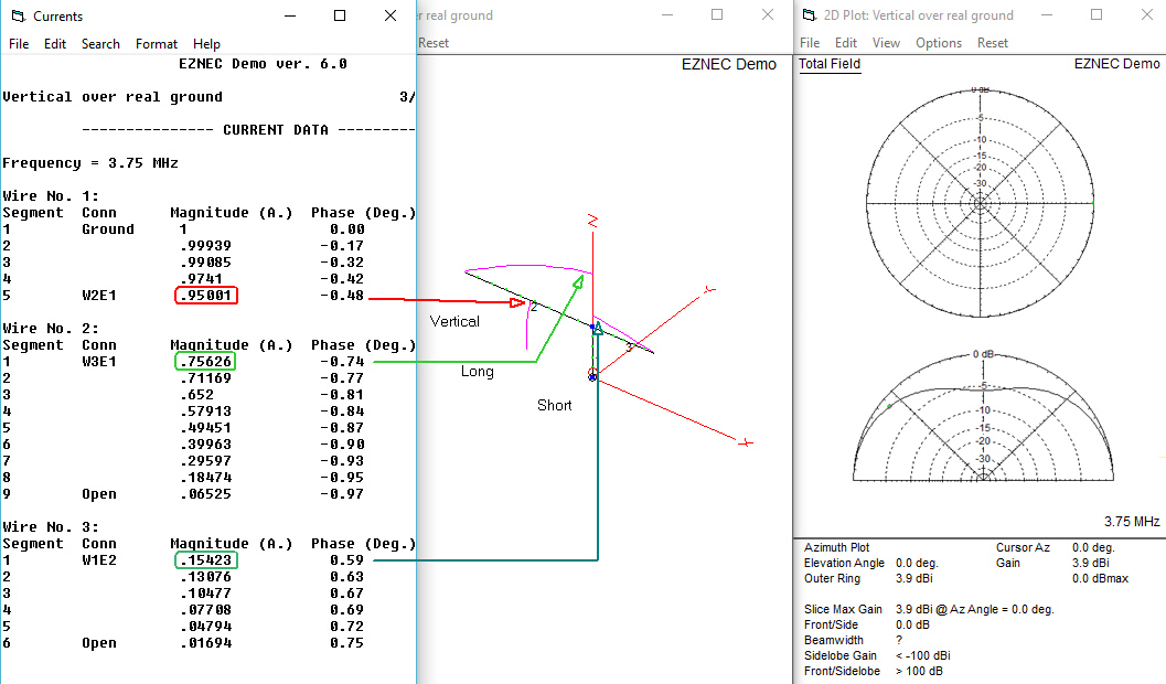
If you inspect the antenna element currents you get a good sense of
what's going on.
| Antenna Mode Determination
80/75 Meter Currents
The antenna functions as an Inverted L because the majority of the
current flowing in the vertical element continues on to flow to the
longer wire element.
Their dimensions are 20' Vertical and 50' Horizontal thus the current
distribution approximates that of an Inverted L on 80/75 Meters. |
 |
| |
|
| |
|
| 40 Meter Currents The antenna functions as a low height, offset fed dipole.
The oval pattern is a result of the low height.
The current unbalance between the wires causes an oval
shaped pattern 2db side shift.
|
 |
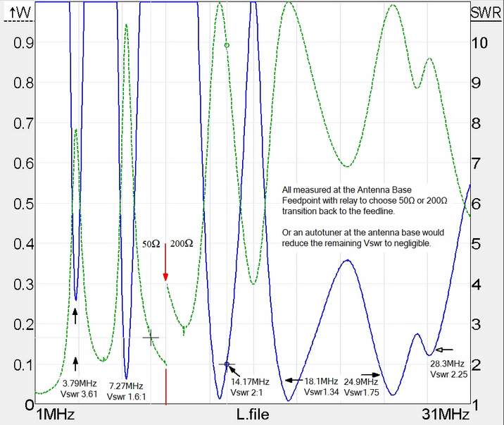
Band Coverage 1-31 MHz
The graph below shows the plots from the Rig Experts AA-55 Zoom Analyzer data
file.
The blue trace is the 50Ω
Vswr at the
flagpole base and it had been rising with frequency so I transitioned 200Ω
Vswr
scaling above 10MHz. The green
trace is the power to the antenna.
I like to keep things simple, so I improved the match on the higher
bands with an 1:4 Z
Step Up transformer at the base of the flagpole, that's my 1st choice rather
than involving frequency
selective networks.
Here is a graph I made early on in the testing. I use the 1:4 Z Step Up
transformer when it provides an advantage.
So,
this is an almost all HF band antenna, no-tuner antenna.
 |
|
Frequency is plotted across the base line and you can see the Vswr
dips are marked beginning at 3.79MHz on up to 28.3 MHz. The
Green
trace is the Power delivered to the Feed Point through ~70' of Buryflex
coax.
The worst case is ~70% (1.5db loss) at 3.79MHz with 50Ω
drive Z.
At 7.257 MHz the Green trace indicates 95% of the power gets to the
load.
Along the base you will see a Red line. To the left of the line the
50Ω
coax connects to the base of the flagpole.
To the right of the line the 4 to 1 Un-Un steps the Z to 200Ω
and observe the Vswr dips are deep and the power to the load is high. |
My station:
I use an Icom 7300, just a dandy
transceiver, BUT
If the Vswr at the antenna
connector of the 7300 is above ~ 3.2:1 the 7300 won't tune in normal 100 watt mode.
Very
inconvenient!
There are mods that you can make so
that the Vswr threshold will be higher, but there goes the warrantee and resale
value.
I partially solved the problem with that 1:4 Un-Un at the Flagpole base.
Choice of Un-Un is
yours, I salvaged the ferrite rod and coils from an old W2AU 1:4 Un-Un and it works OK. I have operated
it with
800 Watts (SSB) without problem.
In the QST article you can see that I have a "remote box" and one of the
relays in the remote box connects the 1:4 Un-Un Z step-up transformer directly
to the flagpole.
It provides a better match in the "trouble spots" so that the Icom 7300 transceiver can operate in
"normal" 100 Watt mode rather than "emergency" 50 Watt mode.
I am very comfortable with this
solution to the Z matching challenge.
Here is my "cheat sheet" for when to use the 4:1 Step-Up.
Advantage on
30, 20 and 15 Meters
using the step up UnUn.
On 10 Meters there is an advantage above 29.000MHz (not an part of the band I
frequent).
|
50Ω
Mode; Coax Direct to Flagpole |
|
200Ω
Feed Mode;
Coax to 1:4 Step-Up
UnUn at the
Flagpole |
|
Band, Meters |
Frequency, MHz |
Vswr At Xcvr Antenna Connector |
Auto Tune 100 Watts |
Emergency 50 Watts |
|
Vswr At Xcvr Antenna Connector |
Auto Tune 100 Watts |
Emergency 50 Watts |
|
|
80 Low end |
3.5 - 3.7 |
>4:1 |
|
Yes |
|
|
|
75 Hi end |
3.7- 4.0 |
<4:1 |
Yes |
|
|
|
60 |
~5.35 |
6:01 |
|
Yes |
|
|
40 |
7.0-7.3 |
1.5 |
Yes |
|
|
2.25 |
Yes |
|
|
|
30 |
10.12 |
5:01 |
|
Yes |
|
4.5 |
Yes |
|
Advantage |
|
20 |
14.0-14.35 |
4:01 |
|
Yes |
|
|
Yes |
|
Advantage |
|
17 |
18.1 |
2:01 |
Yes |
|
|
4.5:1 |
|
Yes |
|
|
15 |
21.01-21.44 |
5:01 |
|
Yes |
|
|
Yes |
|
Advantage |
|
10 |
28-29 |
2.5:1 |
Yes |
|
|
|
Yes |
|
|
|
10 |
29 - 29.7 |
3.5 |
|
Yes |
|
|
Yes |
|
Advantage |
|
6 |
50-54 |
1.7:1 |
Yes |
|
|
|
Yes |
|
|
160 Meters, the next challenge and my true goal.
Before I start in discussion of matching the antenna for 160 Meters, it's important that you know that
short verticals, even with top loading are not going to be gain antennas.
In fact they suffer an overall loss of 10 or 20 db compared to 1/4 λ
verticals.
Fortunately, modern receivers have lots of receiver gain, so on "low noise nights" you
will hear many stations.
Power is cheap especially if you are running a tube amp. The advantage of the
tube amp is that the
Pi section outputs are very load tolerant so you won't need a
hi-power tuner and transmission lines are have very low loss at 1.9MHz.
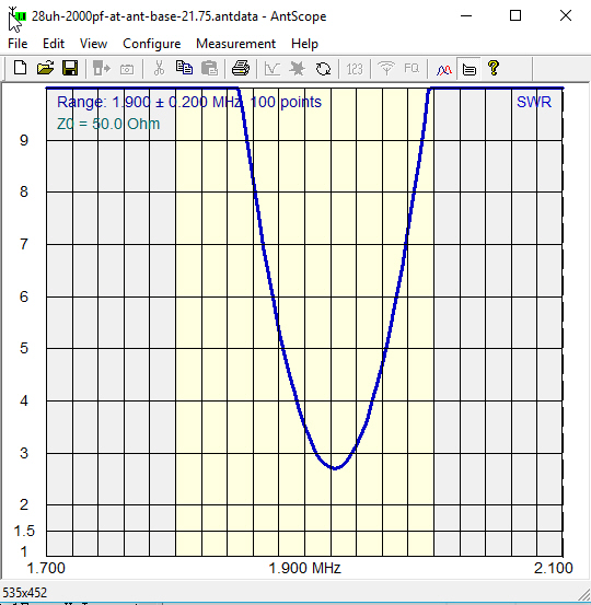
Cutting to the chase... Here is how I matched this really short antenna from 1.8 to 2.0MHz.
I chose a two stage approach to match the very high Vswr at the hi and low
ends of the 160 Meter band.
1st, add an L/C pair, tuned around mid band, ~1.9MHz, and connect through a
relay to the flagpole base (remote box).
Note, the capacitor is connected in shunt across the coax feed line, C is ~2000pF and L is ~28uH
is connected in series to the flagpole.
At 100 Watts, the C voltage will be
about 100V peak and the voltage across the L ~ 1600V peak. You definitely want to consider some safety sensor.
Measurement with the AA-55 Zoom produced the following Vswr curve. Not bad!
 |
|
The values were; 28uH and 2000pF (on hand) so I connected them to
the flagpole and ran the AA-55 Zoom, here is the Vswr for a 50Ω
input. The network could be optimized (later) but it brought
the 50Ω
Vswr to less than 3:1 at the antenna. |
Next, I connected the flagpole through the L/C network and on through the ~70'
of Buryflex to the shack.
In-shack, the coax ran to a Palstar AT2K T Tuner. Good matches were achieved
from about 1.85 to 2.0MHz. (I ran out of inductor at 1.85MHz).
I had calibrated the AT2K years ago so I knew the
dial values vs the L and C values.
Then I mathematically transformed the T tuner Cin, Lshunt, Cout,
values to an equivalent 2 element LC network.
The range of L and C values needed was well within the schematic value
range of typical auto tuners. (MFJ and LDG)
Confidence builder, so I converted the graph above and loaded it into
SimSmith.
In SimSmith shown below, read the top row left to right:
L Flagpole load impedance (variable value stored in file)
L1 Inductor at Flagpole base
C1 Capacitor at Flagpole Base
T1 Buryflex 50
Ω
feedline 70 feet
LC1 Land C provided by the Icom 7300 tuner
G the Icom 7300 Transmitter Power Amp (set at 1 Watt)
The graph shows the result at 1.89MHz, almost 88% of the power is applied to
the flagpole and the Transceiver Vswr is ~1.2:1.
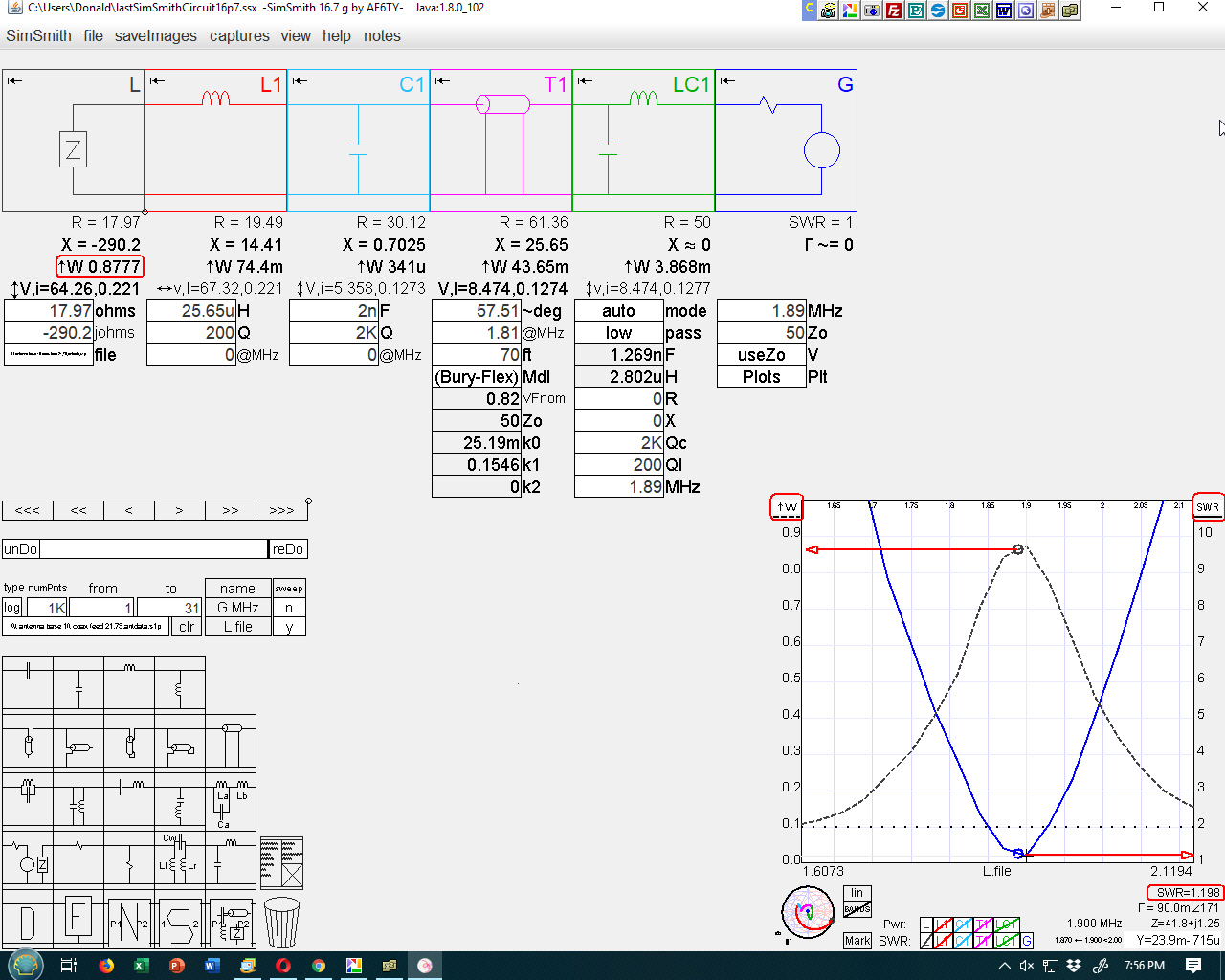
SimSmith is a Smith Charting tool written by
Ward Harriman AE6TY
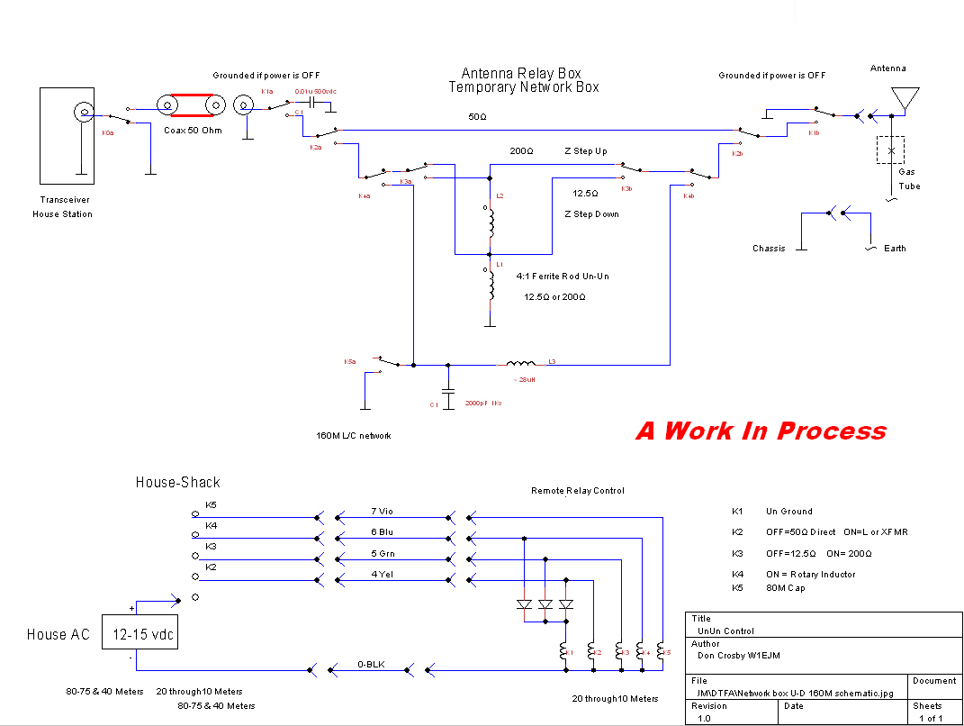
Remote Matching Box Schematic