Antenna
Contest Submission, 80 through 10 Meters
Submitted
by:
Don Crosby, W1EJM,
2128 Sansores Street,
The Villages, Fl. 32159
w1ejm@arrl.net
Table
Of Contents
Antenna
Contest Submission, 80-10 Meters
Narrative
Predicted
Performance Graph from Models
NEC Model Files
Multi-Low Vswr vs Lengths, Example 10 Meters
(28.5MHz)
Installed
Performance
Data Graphs Plot of Vswr Data Spread Sheet
Sub
Assemblies, Photos and Descriptions
Mast Pulley Box Photos and Operations
Motor Box Photos and Operations
Hi Grip Pulley Photos and Discussion
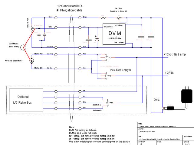
Control / Readout Box Photos and Schematics
Mechanical Sketches and Parts Lists
Optional 160Meter L/C Network
Mechanical
Details
Droop
Deflection
Sub
Assembly Dimensioned Sketches and Parts Lists
Mast Pulley Box
Motor Box
Safety
Errata
Advanced
Options Discussion, not a part of the basic design contest entry. pgs 16 - 21
Antenna Contest
Submission, 80 through 10 Meters
80 – 10 Meter Motorized Inverted “L” Antenna, Low Observability, Legal Limit, No Tuner Needed
Small lot, lack of trees and deed restrictions all made it difficult to cover the HF bands at my QTH. Here is how I worked around those limitations with an all band, legal limit, no-tuner, “low observability” antenna.
This Motorized Inverted “L” antenna configuration allows the length of the flattop to be adjusted from my operating position so that the antenna feed point is at or close to resonance on any HF band. This design results in a Vswr of less than 2:1 at the antenna base, anywhere on the bands with the exception of 75meters. At 2.4:1 Vswr, on 75m is in the range of most XCVR internal auto-tuners. This antenna has been in daily use at my QTH for ~2 years.
The sketch below indicates a "clothesline" configuration where a movable wire element and a monofilament support element are used to put the proper length of flattop wire in place for an Inverted "L." The remaining wire runs down the outside of the Flagpole, over a drive pulley and attaches to the monofilament to continue back to the top of the Flagpole, then out to the "turn-around" pulley and attaches to the wire.
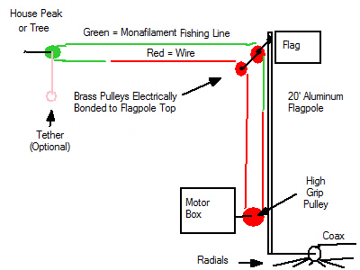
The 80 - 10 meter version of the antenna requires a 55' open length for the flattop and will require 8 or more 30' radials at the base feed point of the mast. If you can accommodate a flattop length of 85', the antenna will provide omni or broad side azimuth on 40 meters and can be tuned to work efficiently on 160mtrs.
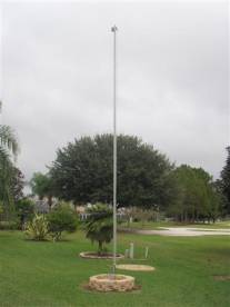
The vertical element of the "L" is a 2" diameter aluminum mast with 0.065" wall thickness (repurposed from a commercial ham Flagpole antenna.) The mast supports one end of the wire flattop while the far end of the wire flattop was attached at a high point on the home structure. The mast is topped with a Dual Pulley Box for the right angle wire turns. The distance between the mast and the far end high point must be in the order of 55' to reach the 80 meter band. The mast is isolated from ground and is fed at its base with 50 ohm coax. This antenna uses radials and has been in operation daily at my QTH for ~ 2 years.
The Motorized Inverted “L” mitigates the need for a tuner. You will achieve coverage to 3.5MHz with the flattop extended to 55’ then reach 4.0MHz with the flattop shortened to 43'. Higher frequencies are satisfied with shorter flattop lengths and achieve lower than 2:1 Vswr at the base feed point. On 75meters, with Vswr at some value above 2:1, a network might be handy, but that need could met with a single fixed L/C added at the feed point by a DPDT relay.
When the wire is withdrawn to its minimum length 2x20' will
reside next to the vertical mast and 2x7.5' will run out in parallel from the
20' top dual-pulley assembly.
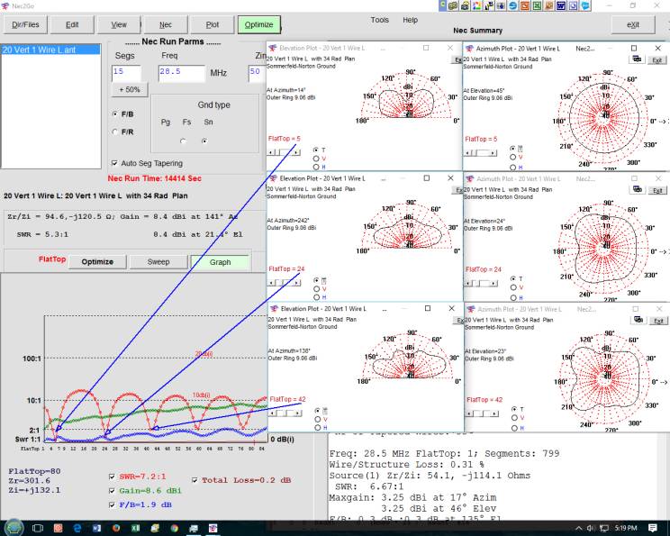
Predicted Performance from NEC Models:
4Nec2 and Nec2Go modeling programs were used for this antenna and files for each are included herein.
80-10Meter performance is predicted with 55' of flattop. The graphs below are shown for lengths of 85' but are marked for the use with 55' wires, the difference being that the 85' Flattop provides broadside gain on 40 meter and the capability of 160 meters (with and L/C network) while the 55' (and less) antenna operated 80-10Meters without
a network.
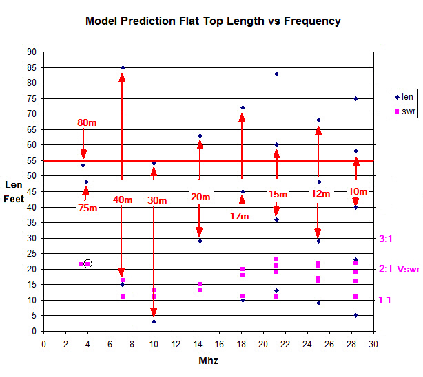
Reading the graph.
The left vertical scale is Flattop wire length in feet. The right vertical scale is Vswr
The black diamonds are points of resonance. These are read on the left vertical scale.
The pink squares denote Vswr and are read on the right vertical scale.
If your interest is the full 85’ flattop length version of this antenna, the information is presented in the full graph.
If your interest is the 55’ version, locate the red horizontal line at the 55’ mark on the left scale and read down from there.
Examples:
A) 30m using 55’ flattop version: locate the red vertical “arrow” line marked 30m. At each end there is a black diamond. Read these positions on the left scale to determine there are 2 points of resonance: one at ~3’ and a 2nd at ~54’. Locate the pink squares along this 30m “arrow” and read Vswr of ~1.1:1 and ~1.3:1.
B) 15m using 85’ version: 4 points of resonance: ~13’, ~36’, ~60’, ~83”. Vswr for any of these points of resonance is ~2.3:1 or less.
4NEC2 file: Vari-L_32r.nec
Nec2Go file: 20
Vert 1 Wire L.ant (30 day Demo
available at www.Nec2Go.com )
Installed
Performance Data:
Instruments
used; MFJ-259b, Autek AV-1, Datapulse Precision 50 ohm Load Standard

Reading the Empirical Data graph:
A) Start at 75m mark, 4.0MHz look left ~43', 3.75MHz 48', 3.5MHz 54', then look down for the “pink bar/circled" and to the right for Vswr of 2.4:1 measured at the antenna feed point. So the Vswr is 2.4:1 between 3.5 to 4.0MHz by lengthening the wire from 43 to 54'; full coverage on 75/80 meters without network.
B) 40meters, 2 solutions: 10' and 82' with Vswr of 1.6:1 and 1.2:1, so 10' would be extended on the short antenna.
C) 80/75meters: 43-54' with Vswr 2.4:1 (Circled) so full band coverage would be achieved on the short antenna.
D) All bands above 40 meters meet the low Vswr while using flattop lengths less than 55'.
Optional w/relay controlled With L/C (Rectangle). Measured performance: See notes on 80/75 Network below.
- 80/75meters, Vswr 1.1:1 a fixed L80/C80 marked With L/C 3.5, 3.6, 3.7, 3.75, 3.8, 3.9 and 4.0Mhz Diamonds
- 160meters, 69'-80' with Vswr 1.5:1 a fixed L160/C160 marked With L/C 1.8 to 1.9MHz Diamonds
With 60' of coax run back to the operating position I operate 80m through 10m no tuner (legal limit if needed). The Vswr is down a bit at my operating position for frequencies above 20MHz as would be expected.
Vswr Spread Sheet
file: 80 ft Vari-L RAW Data.xls
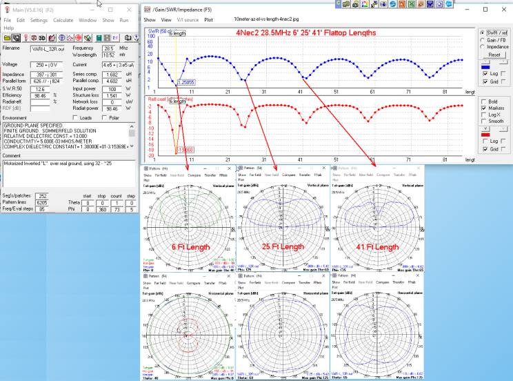
Multi-Low Vswr vs Lengths, Example 10 Meters (28.5MHz)
NEC Plots:
28.5MHz Multi-Low Vswr lengths were evaluated with both 4Nec2 and Nec2Go modeling software. The results below indicated that both modeling engines were in agreement.
The performance models for 28.5MHz where the antenna exhibits Az/El Pattern Gain as a function of lengths.
Vswr measurements correspond with the lengths below.
An experimental method to verify Gain / Pattern was not available other than a few contacts I made where the longer lengths helped a bit.
4Nec2 Software Plots:
Nec2Go Software Plots:
Patterns are very similar to the plots from the 4Nec2 plots.
Sub Assemblies:
Photos and Discussion
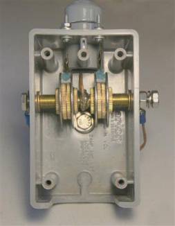
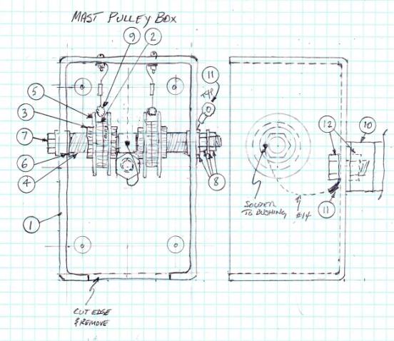
Mast Pulley Box, Operation
RF contact between the wire and the mast is accomplished using a homebrew mast pulleys box.
The "pulleys" are made up of solid brass knurled nuts (for antique lamps).
The pulley shaft is 'hot' with RF and its connection is "bolted through" to the mast.
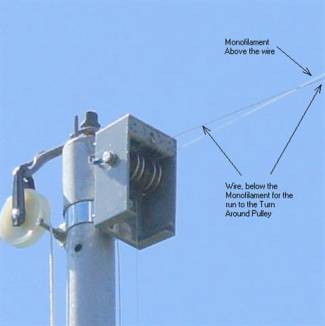
The wire and the monofilament exit the box in the same horizontal plane. The weight of the wire causes the wire to droop below the monofilament thus preventing tangling. In the vertical plane, the lines drop parallel to the mast and they are separated by ferrules (sleeves) located midway down the mast. Tension keeps these lines apart, thus tangling has not been an issue. Normally a cover is used, but these photos were taken for explanation only.
The 'blue' items are GUM Proxabrush Go-Betweens for tooth cleaning. In this application they only serve to prevent the wire and monofilament from 'jumping' the pulley while the mast is being erected.
Once erected the Go-Betweens are above the plane of the wire and the monofilament.
~#21awg 1x7 Bare Copper Trolling Wire, 30 lb test, .028 in American Fishing Wire p/n BCU030-7
Monofilament; 20# or 30# test
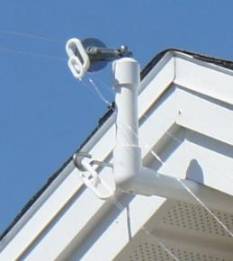
Far End Turn
Around Pulley
1- 2" Plastic Clothesline Pulley, fixed mounted to structure, see Tethering text
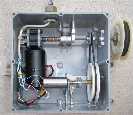
Motor Box, Operation
Note the slight tarnish of the lead screw, it shows the effect of 2 years of Florida outdoors.
Right Angle DC Gear Motor is a surplus 12vdc auto power seat motor, readily available.
A common plumbing "O" ring couples the drive shaft to the readout pot through homemade pulleys.
Homebrew Hi Grip Output Pulley provides slip free coupling to the wire/monofilament.
Multi-Turn Pot, output voltage is scaled to read out in Feet
(An advanced version uses a home brew magnetic encoder with microprocessor readout in place of the pot.)
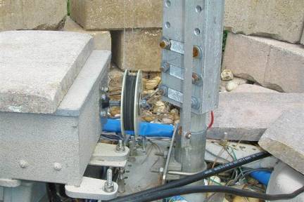
Motor-Box at Mast base, As Built
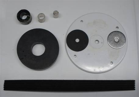
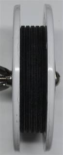
Hi Grip Pulley, Detail, As Built
Key to preventing slippage at the wire/monofilament drive point interface is to have a Hi Grip there.
The High Grip Pulley is made up of smooth sided guides, a center rubber spacer, hose material spacer, tubing spacers and a Grooved Serpentine Belt surface. Metal parts are Stainless Steel.
Assembly on the ¼-20 x 6" Stainless Steel drive shaft is as follows:
¼-20 SS Nut, Lock washer, 1" Washer, 1" Rubber Washer, 4" White Round Ceiling Box Covers, 3 concentric spacers, 3" Disk-Rubber-Seat, 4" White Round Ceiling Box Covers, 1" Rubber Washer, 1" Washer, Lock washer, ¼-20 Wing Nut
Parts Lists:
Hi Grip Pulley
2- 4" White Round Ceiling Box Covers www.Lowes.com Item # 181585 Hillman # PBC300GY
2- ¼ id x 1" od Rubber Washers
2- ¼ id x
1" od Stainless Washers
1- ¼ x20 Nuts Stainless
2- ¼ Lock Washers Stainless
1- ¼-20 SS Wing Nut www.Lowes.com p/n 409445 Hillman # 126893
1- Disc-Rubber-Seat-3 inch www.sprinklerwarehouse.com p/n 6758-G or 3” OD x ½” Plastic (jar) Cap
1- Automotive Serpentine Belt, www.autozone.com Dayco 5050345, cut to circumference
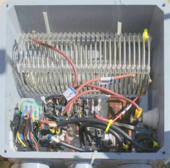
Readout Box,
Simple, As Built
This simple control box shown below has been in use for the last 2 years. It contains a DVM readout which is calibrated in Feet, a Momentary DPDT switch to increase or decrease the wire length and a rotary switch for controlling an L/C network box (160m). Basically, the network box isn't used because on 75/80 meters the Vswr is low and both my XCVR and legal limit amplifier work well without the network.
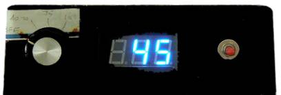
Control Box:
Simple;
12vdc 3amp Power Supply brick, regulated
DC LED Voltmeter Module www.nyplatform.com p/n DYB56-99-Blue
DPDT Center Off, Momentary/Momentary Toggle Switch
Enclosure, small project box
Wire
Details:
The "low observability" concern was one of the key items in this design. To have "low observability" necessitated the use of small diameter wire, no traps, loading coils or other visible items (stubs etc.) to draw attention.
The contact method dictated that bare wire be used. 7 strand copper #21 is used.
The #21 requires careful handling to prevent a kink, but its 0.028"dia. is very difficult to see at a 20' height. It has the benefit of being very light so tension of only 1# is needed to limit center droop to ~1' which is the minimum droop recommended for a 55' run. The monofilament line also is tensioned at 1# but will only droop < 2".
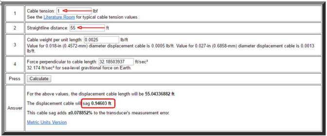
The droop (vertical displacement) is essential to prevent the wire and the monofilament from twisting. At the far end, the "turn-around" pulley is set up to have the wire below the monofilament line. In the event that the "turn-around" pulley can't be fixed to a structure, a "tether line" is mentioned in the sketch. The tether is either weighted with a few ounces or is tied off so that the pulley can not flip, thus the ‘wire low, monofilament high’ orientation is maintained.
During of 2 years of operation and frequently at legal limit SSB there has not been a wire failure due to heating. ~#21awg 1x7 Bare Copper Trolling Wire, 30 lb test, .028 in American Fishing Wire p/n BCU030-7
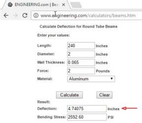
Mast Bending
The deflection is 4.7" with 0.065" wall. The load on the mast is 2# force in the case of #21 wire and 55' wire run. It's recommended that new construction be done with 0.125" wall thickness material.
Sub
Assembly Dimensioned Sketches and Parts Lists
Motor
Box, As Built

Parts Lists:
1- Weatherproof Junction Box 8x8x4 www.Homedepot.com Item #500015 Cantex Model# E989N-CAR
1- Rt. Angle Gear Motor www.mpja.com p/n 33085 MD $14.95, requires shaft length mod
1- 1" Rt Angle Corner Brace used as motor mount, (salvaged)
1- Flex Coupling 8mm* to 6.35mm (1/4 inch) HD www.mpja.com Item # 32565, *requires mod, see text
1- 1/4" Bore Bottom Tapped Pillow Block www.Servocity.com p/n 535150
1- Thrust Bearing; 1/4" Bore, Face Thru-Hole Pillow Block www.Servocity.com p/n 535110
2- Hex or Round Stand Offs www.Lowes.com
1- ¼"-20 x 36" Stainless Steel Threaded Rod www.HomeDepot.com Item # 72627 Everbilt #802477
1- Instrument Box Case Foot Bumpers, 1" dia with ¼ " dia shaft pass thru
1- ½" Electrical Watertight Feedthru www.Lowes.com Connex 49092
Pot Readout, see text
1- 10 Turn Pot for 55', 20 Turn Pot for 85'
1- ¼ x 20 Threaded Hub, www.Servocity.com p/n 545468
1- Plastic tubing, used as slip coupling
2- Small Hose clamps for slip coupling
1- 4" Plastic Clothesline Pulley for Pot drive, grind off excess lip for 3.5" finished diameter.
1- "O" Ring 11" www.allorings.com p/n AS568A -
276 or www.Lowes.com p/n Danco Assortment #3
Mast
Pulley Box, As Built
Mast Top Pulley Box Assembly Parts
ID Qnty Description
1 1-
Carlon, 19 cu. in. Type FS Non Metalic
www.Homedepot.com Item # E980FFN-CTN
2 4- 1" dia. Knurled Locknut, 1/8F thread size www.antiquelampsupply.com p/n 20714
3 4- 3/4" dia. Knurled Brass Locknut, 1/8F thread size www.antiquelampsupply.com p/n 20712
4 2- 1" 1/8 IP Solid Brass, Threaded Nipple www.antiquelampsupply.com p/n 22378
5 4- 3/8 x 1.5 ss fender washer - www.Lowes.com Item # 365114 Hillman 830626
6 3- ¼, 3/8, 15/32, ½ Bronze Bush www.Lowes.com Item # 215870 Hillman 882991, 1 center cut to fit
7 1- ¼ -20 x 3 ½ Threaded Bolt
8 x- 2- ¼ -20 ss Washers / 1- Nuts Lock Washer / 2- Nuts
9 1- GUM Proxabrush Go-Betweens (6 / pack) (Pharmacy), attach to box w/ crimp extension
10 1- 1-1/2-in Rigid Clamp, www.Lowes.com Item # 108635
11 2- ¼"
Solder Lugs for tag wires to clamp
12 1- ¼ -20 x
1" Threaded Bolt / Nut
Safety:
RF voltage is present at ground level on the antenna mast so precautions are taken. When I activate the main switch in my shack to power my equipment, the receiver unit of an "infrared driveway sensor" is also powered up. The receiver gives an audible sound to indicate it's operating. The sonic output from the receiver triggers a 'flip flop' and disables the transmitter key and PTT line, thus preventing RF to the antenna. The 'flip-flop' is reset each day using a manual pushbutton at "power on" to return to normal operation. Batteries in the sensor are recharged by a small solar panel.
Errata:
A 2:1 Vswr is generally accepted as the measure of the usable bandwidth of an antenna because most ham transmitters or amplifier accept a 2:1 Vswr. Many are more generous and allow a 3:1 Vswr.
On 80 meters, the Vswr at the antenna base is 2.4:1. At the end of 60’ of RG-213 feedline it’s down to 2.2:1. If you are inclined to use a matching network on 80 meters, tune a “fixed” L/C for minimum Vswr at 3.7MHz. To move up/down the band simply change the flattop length and the Vswr will drop.
The recommendation is to use 0.125" wall thickness Aluminum pipe; 2-10' sections of 2"OD, and 1-8' section of 1.75"OD, 0.125" wall. Cut a 2' length of the 1.75"OD, slide it into the 2" OD sections, then screw it in place. That is far less expensive then my "ham" commercial Flagpole and much better in high wind load conditions. I had used a Flagpole Antenna kit, 0.065" wall, which contained 5 or 6 -4' "slip fit" sections. The flagpole is NOT recommended because of the deflection load at the top of the mast and the multiple weak mechanical coupling between the 5 sections allow the mast to bend appreciably.
Radials:
4Nec2 and Nec2Go programs use the NEC-2 calculation engine and neither of these programs can allows wires (radials) below ground in the model. L.B. Cebik W4RNL (SK) compared modeling results for above and below ground radials using NEC-4 ( in the May 2001 antenneX Online Issue #49) and concluded that when below ground radials were modeled as if above ground, but very close to ground the NEC-4 results were "reasonable enough", so NEC-2 could be used with below ground radials modeled as if they were above but very close to ground.
Theoretical and practical knowledge indicate that an Inverted “L” antenna does not need an extensive radial system. Originally I installed a Flagpole, simply as a vertical, with remote auto-tuner and also installed about 16 radials at turf level. I continued to add radials to until I reached 34 and found that the last 10 or so made little if any difference other the radial system was less influenced by turf moisture changes.
Above/Below Ground Radials: L.B. Cebik W4RNL (SK) authored many antenna articles and did a great deal of NEC based modeling. He occasionally addressed modeling radials above and below ground and believed that above
Caveats:
This embodiment of the Inverted “L” is not robust. Florida is a warm windy place and this antenna has held up well. When high winds are predicted the antenna wire is withdrawn to the “stowed position” where 40 feet of the flattop is side-by-side with the Flagpole, while a total of 7.5’ of flattop is still horizontal. If we had an ice loading condition here in Florida this builder would beef things up.
Fortunately, in Florida, we have Florida
Statute 720.304 which provides for a modest flagpole installation on any
homeowners property, the only limitations being ‘line of sight’ obstruction or
area within an easement.
The
information beyond this point onward is related to the 80/75/160meter option,
the Advanced Motor Drive with Encoder
Box and a Micro-Processor Enhanced Control Box, readout system and diagnostics.
So,
for the sake of brevity the information was not included in the preceding
Antenna Design Contest information, nonetheless, the information provides
incite into the on going improvements that are in process.
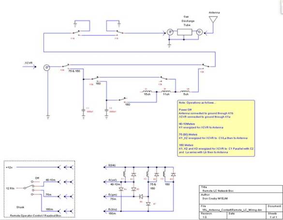
80/75/160
Meter Operation Network (Option)
If you are compelled to get the Vswr below 2:1 at the end of 60' of coax (or 2.4:1 at the antenna base feed point) then the remotely controlled relay circuit below will be needed. Use an antenna analyzer, set the analyzer to 3.7MHz, the antenna to 52' and adjust the coil tap for minimum Vswr (1.1:1 should be achievable). Change the analyzed to 4.0 or 3.5MHz and simply shorten or lengthen the flattop wire and you will note the Vswr will drop to a low value without adjusting either the L or C. Note: if you make the antenna 85' wire length, the circuit also shows the 160 Meter add-on C and tapped L circuit. Use the same tuning method and shorten the wire to move up the band. On 160meters the L/C will cover ½ the band.
80/75
Network Example Modeling Result
The purpose of this model run is to show that adjusting the length of the Flattop for lowest Vswr 3.7MHz and then using the L/C values indicated brings the Vswr at 3.7MHz to ~1:1 then moving to either end of the band and adjusting the Flattop Length brings the Vswr down to ~ 1.3:1 or less, so a single L/C pair satisfies low Vswr at any frequency in the band by adjusting the Flattop length using the remote controlled motor drive.
I used 2 modeling tools, one with 32- 26.75' radials and the other with 33 radials of ~25' so these are not exactly equal models, hence the small differences in L/C and Vswr results.
4Nec2 Model: Vari-L_32r.nec Uses 32 26.75' radials
C/L Network similar, Shunt Capacitor Input to Series Inductor Output:
1655pF, Series: 0.754uH, Q=225
Vary Flattop Length from 48.2 to 58.4 feet provides low Vswr
Freq Length R X Vswr
4 48.2 41.3 -j3.9 1.26
3.7 54.0 49.3 -j0.57 1.01
3.5 58.4 44.6 +j5.9 1.18
Nec2Go Model: 20 Vert 1 Wire L.ant Uses 33 radials of 9' to 33' avg. ~25+/-
Network Center Freq 3.7MHZ chosen, using a Shunt Capacitor Input to Series Inductor Output:
1068pF, Series: 0.99 uH, Q=225
Vary Flattop Length from 46.28 to 55.8 feet provides low Vswr
Freq Length R X Vswr
4 46.28 45.4 -j8.8 1.2
3.7 51.7 49.9 +j0.1 1.0
3.5 55.8 53 +j6.6 1.1
Advanced
Motor Box with Magnetic Encoder (Option)
The choice was made to use a low resolution magnetic encoder where the magnets are mounted to a disk which is centered on the main power shaft of the Motor Box. Thus, there isn't any lost motion in the readout, merely the low resolution penalty which is about 3" of flattop wire position uncertainty. Pot readout is supported for diagnostics.
Advanced Motor Box Assembly
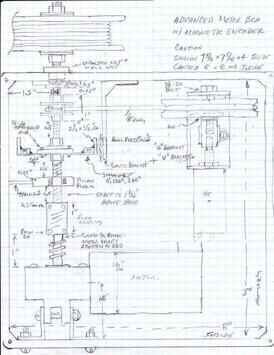
The Thrust Bearing is mounted 2" above the "floor" of the box and 1.5" from the inside wall of the box.
The Shaft is set to run true to those dimensions throughout it's length.
Pillow Block spacers are sized to maintain the shaft 2" x 1.5" path.
Motor mounting brackets are marked and drilled in place.
The "O" Ring is installed, tensioned a bit then
the Pot bracket is marked and drilled in place.
Parts List
Advanced Motor Box:
1- Weatherproof Junction Box 8x8x4 www.Homedepot.com Item #500015 Cantex Model# E989N-CAR
1- Rt. Angle Gear Motor www.mpja.com p/n 33085 MD $14.95, requires mod, see text
2- 1" Rt Angle Corner Braces, Stanley-National Hardware N236-037 / N113-027 www.Lowes.com
1- Flex Coupling 8mm* to 6.35mm (1/4 inch) HD www.mpja.com Item # 32565, *requires mod, see text
1- 1/4" Bore Bottom Tapped Pillow Block www.Servocity.com p/n 535150
1- Thrust Bearing; 1/4" Bore, Face Thru-Hole Pillow Block www.Servocity.com p/n 535110
2- Hex or Round Stand Offs www.Lowes.com
1- ¼"-20 x 36" Stainless Steel Threaded Rod www.HomeDepot.com Item # 72627 Everbilt #802477
1- ½" Electrical Watertight Feedthru www.Lowes.com Connex 49092
1- 137181 Hillman 880511 ¼-20 well nut for shaft pass thru (used as moisture seal) * remove brass thread
Pot Readout, see text
1- 10 Turn Pot for 55', 20 Turn Pot for 85' see text
1- ¼ x 20 Threaded Hub, www.Servocity.com p/n 545468
1- Plastic tubing, used as slip coupling
2- Small Hose clamps for slip coupling
1- 4" Plastic Clothesline Pulley for Pot drive, grind off excess lip for 3.5" finished diameter.
1- "O" Ring 14" www.allorings.com p/n AS568A - 280
Magnetic Encoder Readout for use with uP Controller
2- Mini Reed Switch, SPST-NO www.mpja.com p/n 19500 SW
3- Magnets from name badges, neodymium magnets (household scavenged)
1- ¼ x 20 Threaded Hub, www.Servocity.com p/n 545468
1- 2 ½ " Plastic cap (household scavenged)
Arduino
Micro-Controller Controlled / Readout Box (Option)
A drawback of the "Simple" control box is that Increase/Decrease command is only a switch closure and the motor is "plugged". Thus, wire motion start and stops abruptly and that induces an impulsive motion profile. Micro-controller technology presents the opportunity to control the motions of the antenna wire in a precise way as well as set wire length based on Frequency using a single (pot or encoder) dial with only ham bands in its look-up table.
This uP controller was developed and was demonstrated for a Variable Vertical antenna along with an "operating hardware- show and tell" on Feb 16, 2017 at The Villages Amateur Radio Club, The Villages, Florida, see presentation.
Commanding Frequency:
The "dial up" supports 3.55, 3.65, 3.75, 3.85. 3.95, 5.36, 7.05, 7.15, and 7.25MHz then next would be 10.1MHz etc. up to 29.0 or even 50.5MHz.
So, for instance, to operate around 7.22Mhz, the operator would dial 7.25 and the motor would gradually ramp to speed, then ramp down when the programmed length is approached and then 'creep speed" until the desired length is achieved.
A "calibrate" mode is supported and the "cal" procedure can be done from the operator position. Fail-Safe conditions are monitored such as: over current, not-moving and power status. Conditions are reported on the display and the drive to the motor is shut-down.
Other opportunity exists to such as to control the antenna by interface to XCVR frequency or to use Vswr sensing.
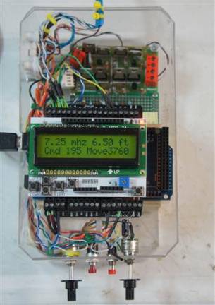
Arduino Micro-Controller Breadboard for Variable Vertical Antenna
|
|
|
Parts List Arduino Micro Board Mega 2560 2x16 Character LCD 5amp H-Bridge Driver Board Potentiometer Momentary N/O Pushbutton Switch Enclosure Not Shown 18vdc 3amp Power Supply brick, regulated 5v Regulator Wall Adapter, 1amp |
Calibration set for Show-n-Tell is 1/3 scale vertical.